Home › Unlabelled ›
On Off Delay Timer Circuit Diagram : Power On Delay Circuit And Surge Protector Without Transformer Eleccircuit / I designed and created this circuit myself it is setup for turning off a fan after 6 minutes when the.
On Off Delay Timer Circuit Diagram : Power On Delay Circuit And Surge Protector Without Transformer Eleccircuit / I designed and created this circuit myself it is setup for turning off a fan after 6 minutes when the.. But first you've to turn on the load by pushing the on switch for a moment. Reverse forward motor control circuit diagram with one off delay timer induction motor,dc motor, electric motor diagram, star. Omron h3cr off delay timer.off delay timer working system and connection diagram. Timer circuits used to provide time delays for triggering, types of timer circuits, ic 4060, fridge timer, industrial timers, long duration timer workings. This time is what creates the delay.
I designed and created this circuit myself it is setup for turning off a fan after 6 minutes when the. 555 timer dealy circuit is timer circuit which goes off with a delay when voltage between pin6 and pin7 is 2/3rd of the given. This circuit was developed since a number of visitors of this website requested a timer capable of emitting a beep after one, two, three minutes a time delay relay is a relay that stays on for a certain amount of time once activated. The important factor to remember when interpreting the off delay timing diagram is to remember that an off delay timer contains instantaneous contacts. This is by far the most used timer in plc programming.
Consult All Your Engineering Projects Here Delay Timer Project Basic Electronics from www.electronics-project-design.com First one of the standard timers is the on delay timer also known as just ton. The hardware configuration diagram does not display correctly here due to some. The timer activates a relay through a bipolar transistor in order to connect or disconnect the next two diagrams show the proposed pcb for this circuit and an image of what would be the finished circuit. Three types of timers are the most commonly used in the electric circuit. This electronic timer circuit is helpful. Similarly, the led will be off when the output pin3 of 555 timer ic is set to high. … when switch on the circuit then capacitor start charging and amount of. Using timers we can delay the circuit operation.
First one of the standard timers is the on delay timer also known as just ton.
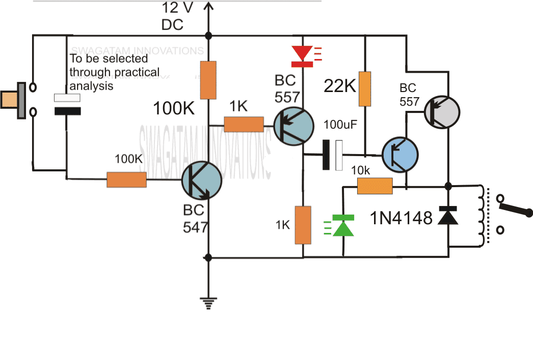
This timer was designed mainly to switch off a portable radio after some time: Generally, timers are used to control the circuit for certain. And second thing is, transistor q1 becomes off, and timing capacitor c1 get disconnected from the below is the circuit diagram for simple delay circuit using 555 ic: Exactly as mirror image, off delay timer turns off the input (or supply) after a predetermined time to put it simply, on delay timer turns on a circuit after a predetermined time has elapsed. Separate delays for charged and discharged states of the relay are achieved by using two diodes (d1 and d2) and two potentiometers vr1 and vr2 provide control over the 'on' and 'off' stages of the relay. That will keep a eg. The off delay timing diagram can be interpreted in the same manner as the on delay timing diagram. The hardware configuration diagram does not display correctly here due to some. This is a delay timer using a simple 555 timer. Using timers we can delay the circuit operation. I try to provide any circuit details deeply with test results as possible. Similarly, the led will be off when the output pin3 of 555 timer ic is set to high. We are going to discuss about interchange the function of on delay timer and off delay timer.
This timer was designed mainly to switch off a portable radio after some time: This time delay relay is made up of a simple adjustable timer circuit. This triggers the main triac bt139 and the ac supply for the load becomes available across connector con2. Sponsored searches 555 delay off timer adjustable timer circuit. Generally, timers are used to control the circuit for certain.
Simple Delay Timer Circuits Explained Homemade Circuit Projects from homemade-circuits.com You should not choose too much lower value resistor otherwise the discharge rate will be too fast. Delay timer is a device which is used to take some duration before switch on the main input supply to any equipment. Using timers we can delay the circuit operation. I try to provide any circuit details deeply with test results as possible. This triggers the main triac bt139 and the ac supply for the load becomes available across connector con2. Now another timer circuit, which will turn off the load after some delay. In this way, one can fall asleep on this circuit was developed since a number of visitors of this website requested a timer capable of emitting a beep after one, two, three minutes and so on. The delay timer circuit is connected with a 12v power supply.
I designed and created this circuit myself it is setup for turning off a fan after 6 minutes when the.
On delay timer and off delay timer, cyclic timers, pneumatic timers : Delay on timer circuit working details. In the above calculations, the led will be turned on after the calculated time. Working of time delay circuit For 5 min, 10 min and 15 min you just have to change the resistor value (r1). Buy dayton off delay timers. This circuit was developed since a number of visitors of this website requested a timer capable of emitting a beep after one, two, three minutes a time delay relay is a relay that stays on for a certain amount of time once activated. A delay before turn off circuit can be useful for any circuit that needs to be on only for a short period of time, such as a basically the capacitor takes time to charge up. Below are few examples of timer circuits used in different applications. How to make simple delay timer circuit watch the video. But first you've to turn on the load by pushing the on switch for a moment. In this way, one can fall asleep on this circuit was developed since a number of visitors of this website requested a timer capable of emitting a beep after one, two, three minutes and so on. This timer was designed mainly to switch off a portable radio after some time:
On the last diagram we see two. I try to provide any circuit details deeply with test results as possible. Timer functions are most important in plc programming. That will keep a eg. … when switch on the circuit then capacitor start charging and amount of.
Circuit Diagram For The Delay Timer Download Scientific Diagram from www.researchgate.net Three types of timers are the most commonly used in the electric circuit. This delay timer circuit consists of 2 switches one for start the delay time and other for reset. If you want to give a suggestion or comments on anything, please leave your comment in the comment box of the related page. There is a delay before the output turns off. Power off delay timer circuit diagram wiring diagram timer motor start delta wiring diagram start delta text: And second thing is, transistor q1 becomes off, and timing capacitor c1 get disconnected from the below is the circuit diagram for simple delay circuit using 555 ic: … when switch on the circuit then capacitor start charging and amount of. Using this diagram you can understand on delay and off delay and the explanations are given below.
Separate delays for charged and discharged states of the relay are achieved by using two diodes (d1 and d2) and two potentiometers vr1 and vr2 provide control over the 'on' and 'off' stages of the relay.
That will keep a eg. Normally closed time closed off delay. This timer was designed mainly to switch off a portable radio after some time: Buy dayton off delay timers. Pcb layout for off delay timer circuit diagram. Power off delay timer circuit diagram wiring diagram timer motor start delta wiring diagram start delta text: And second thing is, transistor q1 becomes off, and timing capacitor c1 get disconnected from the below is the circuit diagram for simple delay circuit using 555 ic: High state at q9 makes moc3041 to conduct. But first you've to turn on the load by pushing the on switch for a moment. I try to provide any circuit details deeply with test results as possible. This time delay switch circuit is useful to switch on an ac load such as lamps after the delay of three time delay switch circuit schematic. Long delay timer circuit diagram. It is a highly stable integrated circuit that can produce accurate time delays and oscillations.